Tell me what ails you,
And I'll go find you the cure
Oh, you're mute, aren't you?
idk, lol
Over a year and half since I bought the Rostock MAX, its calibration is still a bit of a mystery to me. Part of that is my fault, since I've been modding it pretty much continuously since I got it. I can certainly get good performance out of my printer, but it would certainly help to get a better understanding of what causes some of the errors I keep seeing. My printer's a tad different than most, given that I use a magnetic, kinematic coupling to quickly swap out print heads and my z-probe. I use mechanical microswitch for my z-probe, and my usual calibration method is as follows:
- Turn on heat lamp and internal heater. Environment can reach up to 50C without issue
- Heat up bed to around 87C (unfortunately the maximum bed temperature I can reach reliably)
- Swap out my print head for my z-probe
- Take z measurements close to the towers, at locations (0,90), (77.94,-45), (-77.94,-45). For me, the arms are not quite vertical when measuring these locations, but they're very close.
- Adjust endstops for each tower until they are close to equivalent. I usually aim for a 20-30 micron different at most, if possible. I adjust one at a time, and usually I cycle through the towers 2-3 times before I'm happy with my measurements.
- Measure the z height at center and check it against the outer z measurements. Usually, this value will be very close. Otherwise, I adjust the printer radius in the firmware until I'm happy.
- I swap out the z-probe for the hotend and heat it up to temp for whatever material I'm printing.
- I'll use a piece of paper to set the zero z-height where I can feel the nozzle grazing the paper as I'll move it back and forth.
This approach is essentially what the original Rostock MAX assembly guide suggests. At this time, I don't think I can do justice to all the work done on attempts at auto-calibration/leveling (but soon!), so I'll focus on trying to further break down how mechanical errors affect the final print, since these would be the reasons why we re-calibrate over and over.
Where to Measure Z?
In my initial cursory overview of delta kinematics, I looked at the effects of tower movement error. This is effectively the same as poor leveling with an incorrectly-set endstop or tower height. I introduced a range of errors between -1.0 and 1.0 to each of the towers and found the regions of the workspace where the resulting z error was less than a micron difference from that tower's effective error. Most instructions suggest measuring the region directly in front of towers to set the endstop for that tower, so I wanted to see if that was indeed the optimal point to test:
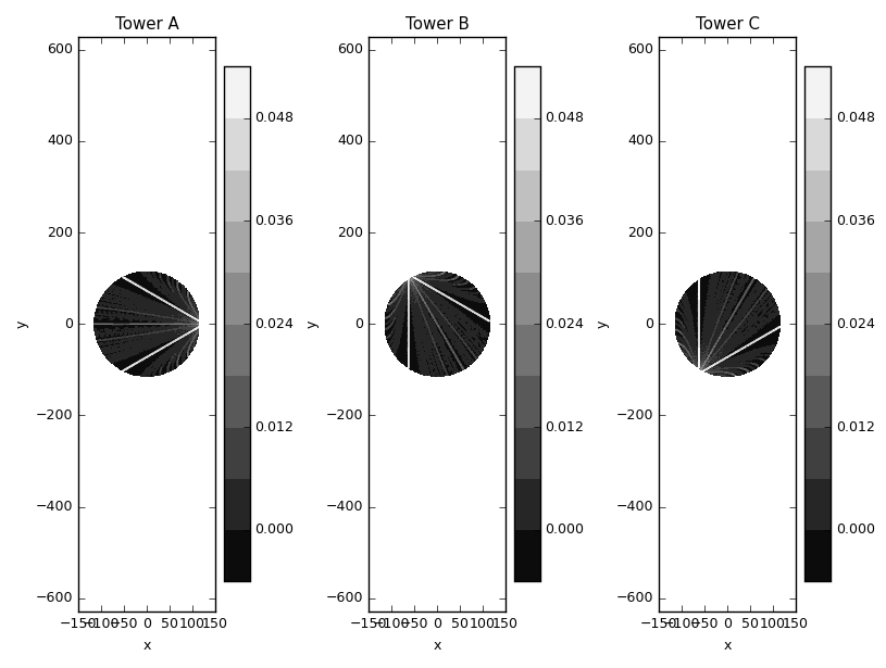
To contour plot above shows the parts of the build space to most commonly have a z error that's close to the particular tower's endstop error. Indeed, for the towers, it looks like it's ideal to probe heights along the edges of the equilateral triangle connecting the towers. Here, I should point out that some attempts at auto-calibration/leveling (including RichC's Marlin implementation) make a point to also probe points opposite the towers, lying on this equilaterial triangle. I still need to go through the code for the current auto-calibration implementations, but this suggests that maybe we can be smarter about where to probe the height instead of just sampling over some even grid.
Sizing Prints Correctly
Improper firmware settings are generally more problematic for deltas than cartesian printers. An error on a cartesian printer can be reproduced the same way across the entire build plate. For example, a part oversized by 0.2mm will be oversized by that amount no matter where you print it on the tray. For a delta, the accumulated error changes depending on where we are on the build plate. Therefore, especially for larger prints, you may have regions that are sized incorrectly, but in different ways, which can make things super problematic.
For stock delta machines with no modifications, the companies will usually tune the parameters in the firmware so that the parts come out close to spec. I still remember that my initial prints from my unmodified Rostock were very good (surprisingly good, actually). After my modifications, I wasn't so lucky, and I'm still not quite there. In general, I think the standard operating procedure is to print a reference block (usually 20 mm along each side) and tweak the arm length parameter until the prints come out as desired. In general, increase the arm length to increase the output size (if your parts are normally undersized). The one really annoying thing I've found is that you'll have to update your effective virtual delta radius after changing the arm lengths, and in doing so, the effective change from the arm length modification also changes.
For example (simulation w/ stock Rostock MAX V1 parameters):
> python -i DeltaPrinter.py
>>> de.dL=1
>>> de.eval(genGrid(20,1),True)
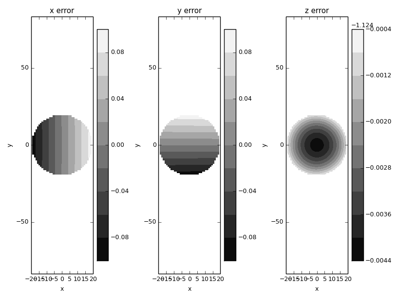
Here, I increased the arm length by 1 mm, and for a specified cylinder of diameter 40 mm, we'd expect the output to actually have diameter around 40.16 mm. However, if you look at the z error introduced by our arm length modifications, we see that we now have a concavity problem. It shows that there's only a 5 micron error, but keep in mind that this is for a 40 mm diameter region. If you were to re-run this for the entire build plate (radius 120 mm), you'd see a z error of 180 microns. Of course, we can accommodate this:
>>> de.dL=1
>>> de.dR=0.23
>>> de.eval(genGrid(20,1),True)
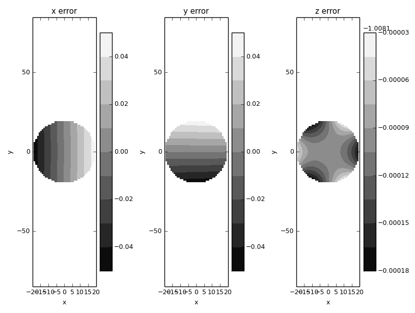
We've reduced that z error to less than 0.1 micron in the 40 mm test sample, but now the output is only oversized to 40.08 mm, half of our intended change from the previous step. To really get it right, we have to keep iterating, until:
>>> de.dL=2
>>> de.dR=0.45
>>> de.eval(genGrid(20,1),True)
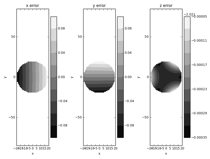
And we now finally have our original change while also accounting for the changes that need to be made during re-leveling. From what I've seen, I don't think there's a way to calibrate for accuracy in xy without printing each part and measuring.
That all said, we can still try and accommodate the necessary adjustments in leveling and look at the final relationship between arm length and print size accuracy. In the following plot, I considered just points within 20 mm of center. I sampled arm length deviatons from -10 mm to 10 mm. For each case, I adjust the printer radius until the z error is less than 5 microns. Then, I find the average ratio of the cartesian error and radius from center. For small objects, this tends to be fairly consistent. I eventually end up with:
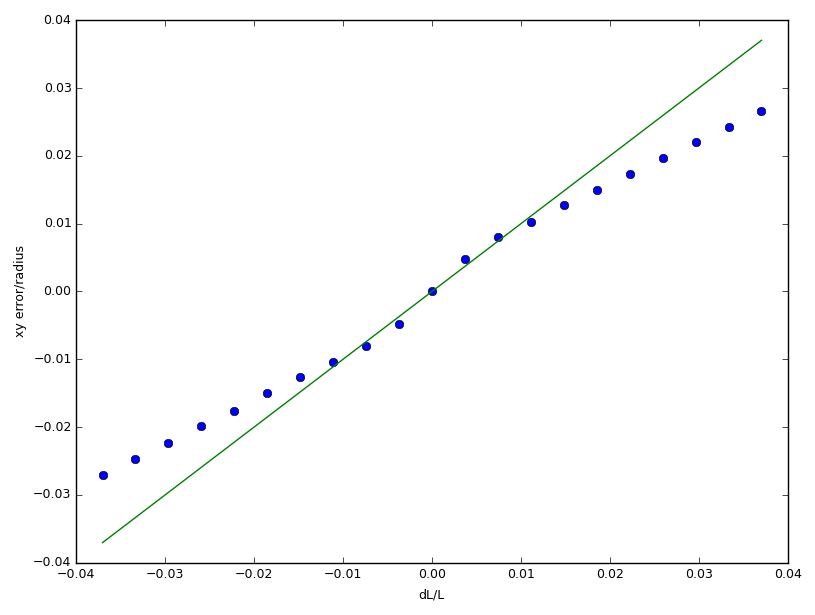
For small, normalized changes in arm length (which is reasonable, since our initial measurements shouldn't be that horrible), there is close to a 1:1 relationship between the normalized errors in arm length and print sizing. For the life of me, I can't find the reprap forum post that suggested this, but I guess the simulation validates that claim. (Note: There are actually error bars plotted above for the cartesian error to radius ratio, but they're 2 order of magnitude smaller than the ratio, so I guess they're too small to show up, which bodes well for us)
One major thing I haven't yet been able to wrap my head around and prove yet is whether or not there's a systematic harmony between all the kinematic parameters. By that, I mean: if I have a delta that's perfectly (and I mean perfectly) leveled across the entire build plate, does that mean it's also dimensionally accurate in cartesian space? Just by playing around with my simulation, I've found that introducing arm errors makes it incredibly difficult to properly level the cartesian motion up to the furthest outer bounds of the workspace. Many of the auto-calibration methods I've glanced at insist on adjusting the arm values from just probe data for the z height. That has always made me wonder if it could inadvertently mess up the cartesian print accuracy, but maybe everything's properly interconnected. I'll try and revisit this after I take a more in-depth look at auto-calibration implementations.